Conversion kit, float chamber venting Carburettor SU HS6
Volvo PV, 120, P1800, 140
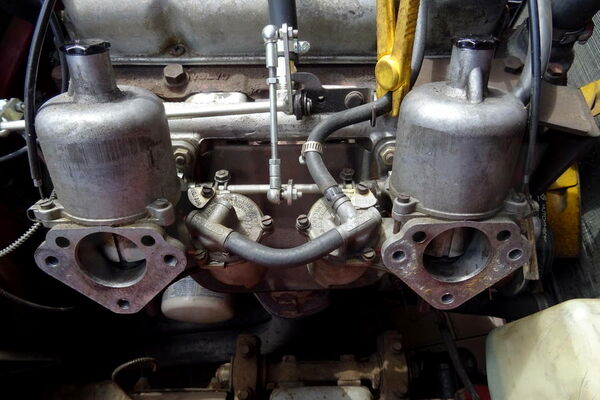
24.11.2021On some SU HS6 carburettors the float chamber ventilation is done through a small hole in the float chamber cover. Here in case of a carburettor overflow the fuel runs over the carburettors and then drips onto the hot manifold and exhaust - fire hazard! With our set you can convert the float chamber ventilation of the SU HS6 carburettors to new float chamber covers with hose nipples, where the fuel is drained off via a drain hose in case the float chamber overflows. As a "side effect" the formation of vapour bubbles is much less problematic and the larger bleed nipples do not clog so quickly. In the following we will show the conversion step by step.

To install the new float chamber covers, first remove the air filters.
Disconnect the fuel line coming from the fuel pump and then pull it off, or pull it off and empty it into a collecting container.
Remove the connecting hose between the two float chambers.
The covers of the float chambers can now be removed after unscrewing the three slotted screws.
The float and needle valves can be reused if they are in good condition. The float must not be leaking. The needle valve must not hook or jam and must of course close correctly.
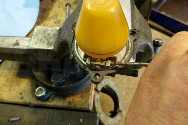
To remove the float, carefully clamp the cover with protective jaws and knock out the bearing pin from the non-grooved side.
Set the float and bearing pin aside and check the needle valve. If the float or needle valves are defective, they must be ordered separately, they are not included in the set.
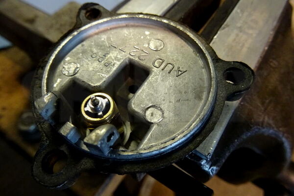
Remove the needle and unscrew the needle seat. Then reassemble the parts in reverse order on the new float chamber covers.
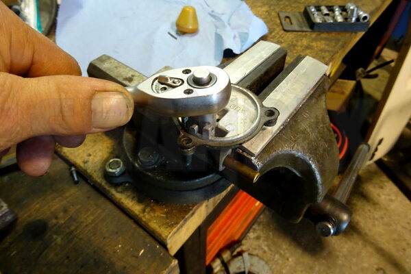
Hammer the bearing pin in such a way that the grooved surface just secures the pin, do not use too much force.
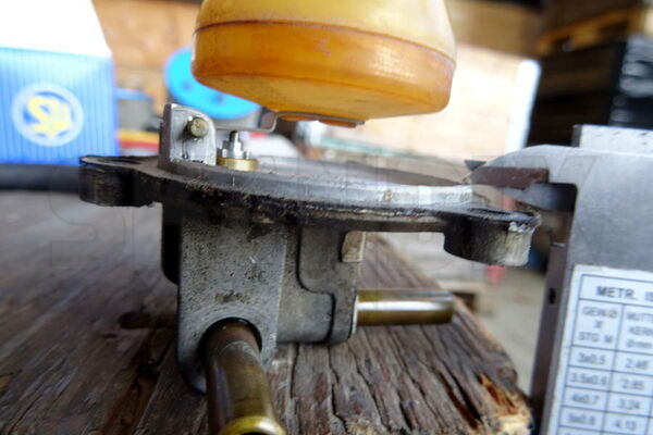
The height of the float of such plastic floats is to be adjusted by bending down the sheet metal flap so that the distance between the lower edge of the cover and the deepest point of the sheet metal flap is between 3.2 and 4.8 mm.
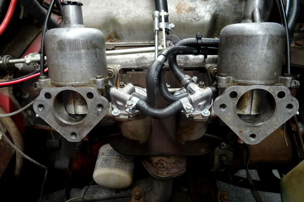
Now the new covers and hoses can be mounted.
The two venting hoses are to be connected with each other using the T-piece supplied. Lay the ventilation hose from there with the enclosed cable ties so that it goes out into the open at a suitable point.
We have laid it around the engine at the front and led it outside on the left side of the vehicle under the master brake cylinder. It must not chafe or be laid near exhaust parts!
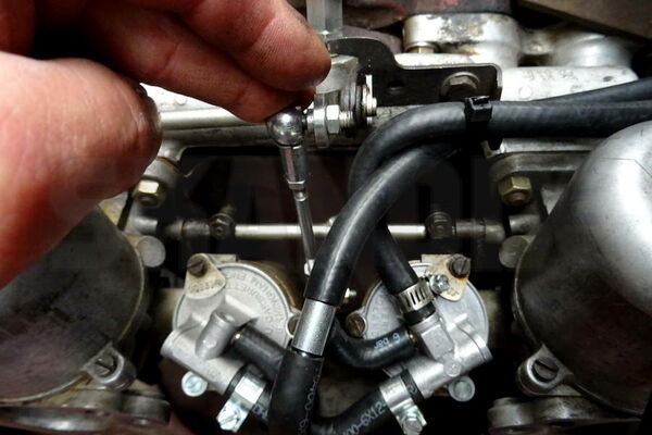
After completion of the assembly, the throttle linkage must be checked for free movement, it must also not scrub on the hoses.
The clamps at the supply line between the carburettors must be set in such a way that they do not bump against the air filters when they are screwed on.
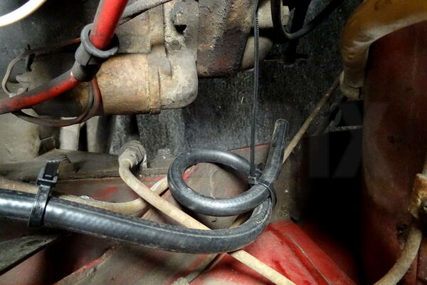
A small tip for the exit into the open air: You should make a loop. Then any escaping or vaporized petrol can collect in the bottom of the loop and slowly evaporate from there. Then you don`t have Petrol stains under the car right away.
- All notes serve only as an example and do not replace the workshop instructions of the automobile manufacturers! All information is supplied without guarantee!
Additional information...
- 1079790: Conversion kit, Carburettor float chamber venting SU HS6