General information for display repairs
Universal
18.12.2023Preparation: Please pay attention to a clean environment and discharge yourself before touching the electronic components, for
example by touching a radiator.
Contact types: There are three different contact variants:
them before installing the display. Attention, the protective films are NOT to be confused
with the silver-colored reflector foils on the back.

The correct orientation of the display is essential for the function
of the display. Most displays have a small nose on the edge. This must be placed
in the notch of the recess for the display. Carefully clean the conductive rubbers and
the contact surfaces of the displays. A speck of dust is sufficient to disturb the contact
between the conductive rubber and the display and then leads to an incomplete display
of the symbols. The same applies to the contact surface between conductor foil and
conductive rubber. If some symbols are not displayed completely later, the contact between
glass and conductive rubber or conductor foil is very often the cause.

Speedometer needles: Depending on the vehicle and instrument, the speedometer
needles may need to be removed to access the display. To do this, use the needle puller by grasping under the speedometer needle and prying it out slowly and
carefully. Particular care should be taken to pry the needle out straight and in axial direction.
When bent, the plastic could break quickly. Heating the needle to around 50 °
C facilitates peeling. Mark exactly the position of the speedometer needles: These must
be used again later.
sheet must be removed after removing the needles. If this is glued on the board, you
can pull it off carefully. In general, the adhesion of the adhesive surface is still strong
enough even after disassembly to be applied again without new adhesive.
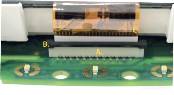
Connectors (2.): Displays whose conductor foils are not ironed but plugged can be
mounted quickly. On the board are connectors in which the conductor foil is inserted.
You can only remove the conductor foil from the connector by pushing the very small
clamping bar (as shown in the picture) upwards until the conductor foil can be removed.
Make sure that you bend the conductor foil as less as possible.
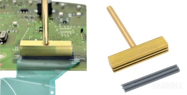
Ironing welding (3.): When ironing a soldering iron with T-soldering tip and the associated
silicone lip is needed. The silicone lip is pressed into the T-soldering tip. Then
the T-soldering tip is mounted in the standard soldering iron instead of the original tip.
There are the T-soldering tips with three different pin diameters of 4, 5 and 6mm depending
on the existing soldering iron.
Now, with a sufficiently large and heated silicone surface, the sensitive conductor foil
can be ironed onto the board. High attention must be paid to a precisely positioned
film, so that the right contacts are also perfectly aligned. At about 70-90 °C and a few
seconds residence time of the T-soldering tip, the conductor foil should adhere to the
board. Act carefully. In the worst case, you
- All notes serve only as an example and do not replace the workshop instructions of the automobile manufacturers! All information is supplied without guarantee!
Additional information...
- Product information: General information for display repairs
18.12.2023, 259 KBytesDownload now

