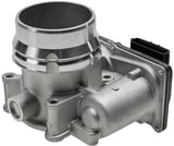
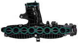
Intake manifold
29.05.2026This installations guide was created on the basis of the Volvo XC60 up to model year 2017. There may be deviations in the procedure for other vehicle models.
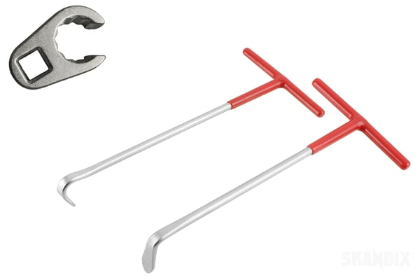
The following materials and tools are required to remove and install the intake manifold:
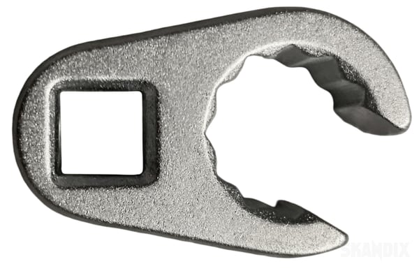
• Crowfoot spanner (1102582)
• Mounting hook (1057172)
Before starting work, the safety instructions for the diesel fuel system must be observed. The engine must be switched off and completely cooled down. The air filter housing and the air intake hoses must be removed as they cover access to the intake manifold. Then disconnect all connectors and fuel lines in the working area until the intake manifold is fully accessible.
Caution: The installation position of all lines and hoses should be documented before removal in order to facilitate subsequent installation. Open lines and connections must be sealed with plastic plugs (1078451) immediately after loosening to prevent the ingress of dirt.
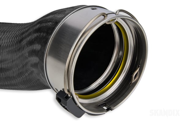
Caution: The contact surfaces must be clean and free of foreign matter. It must also be ensured that the sealing ring is correctly positioned. This step is necessary to ensure a tight connection during subsequent installation.
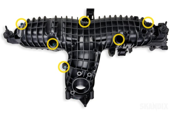
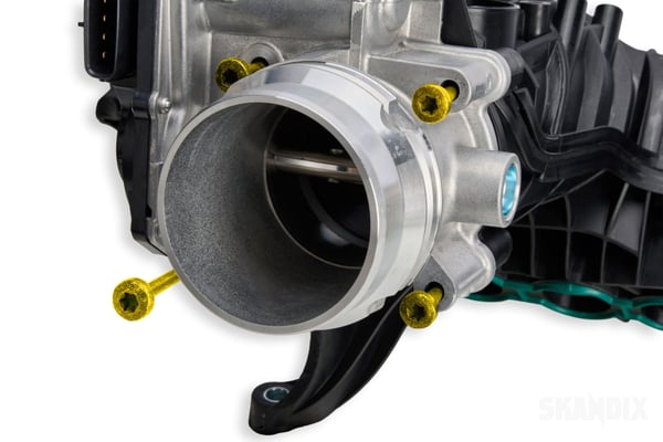
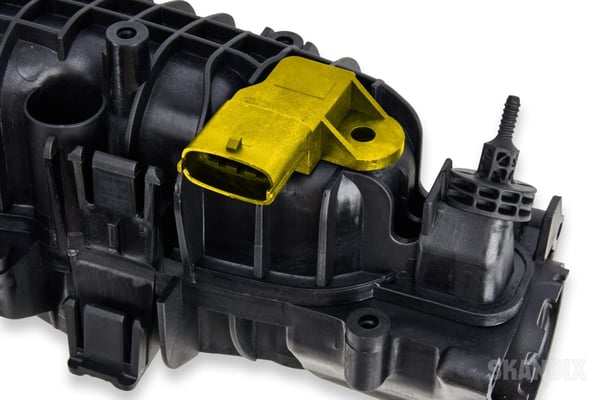
The boost pressure sensor and the associated mounting are removed from the old intake manifold and transferred to the new intake manifold. Ensure that the sensor is seated correctly and that the sealing surfaces are undamaged.
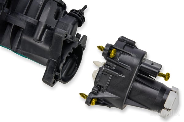
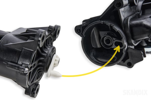
The control element of the swirl flap is now removed from the old intake manifold.
- All notes serve only as an example and do not replace the workshop instructions of the automobile manufacturers! All information is supplied without guarantee!
Additional information...
- Installation guide: Intake manifold
29.05.2026, 534 KBytesDownload now