Driver door lock cylinder
Volvo 850, S70, V70 (-2000), C70 (-2005)
24.02.2022Hints for the removal and installation of the lock cylinder and for the installation of the pin for transmitting the rotation movement to the door lock.
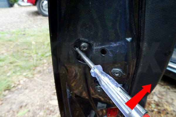
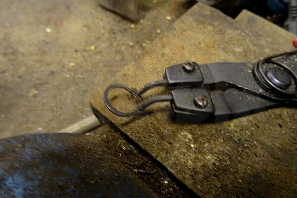
To remove the locking cylinder, lift off the cap outside on the cylinder and remove the pentagonal cover over the screws of the handle at the back of the frame. Now loosen the two visible screws as far as possible, but never remove them completely. Now wiggle the handle a bit so that you can see the retainer spring of the cylinder in the third hole. Now lever the spring up to the back of the door with a small screwdriver as shown in the picture. Insert the key into the cylinder and turn it in any direction and pull the cylinder with the key.
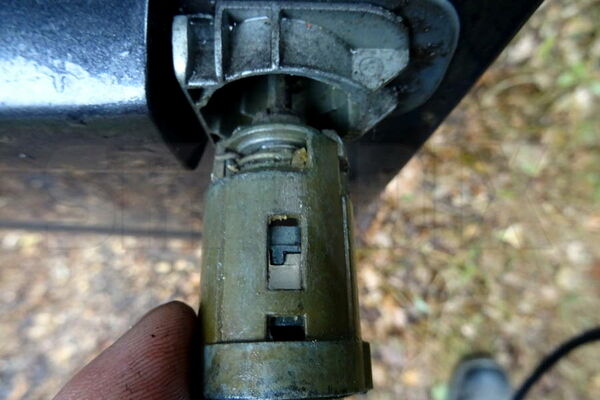
If the cylinder cannot be pulled just like that, help with some penetrating oil. Remember the installation direction when pulling, it can only be inserted as shown in this picture. If you turn it by 180°, the spring has no holding function and it will not fit properly.
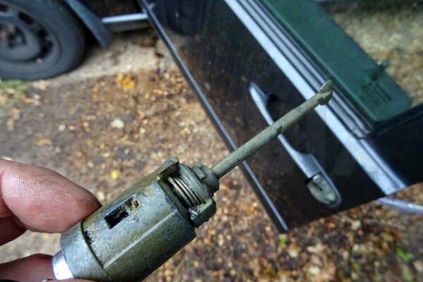
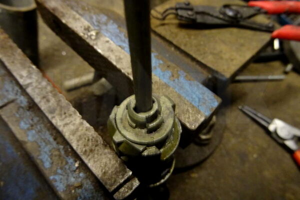
Here you can now see the actuating pin of the cylinder. It transmits the rotary motion to the lock and tends to break off as it ages.
The pin sits rotated 90° and locked in the rear part of the cylinder.
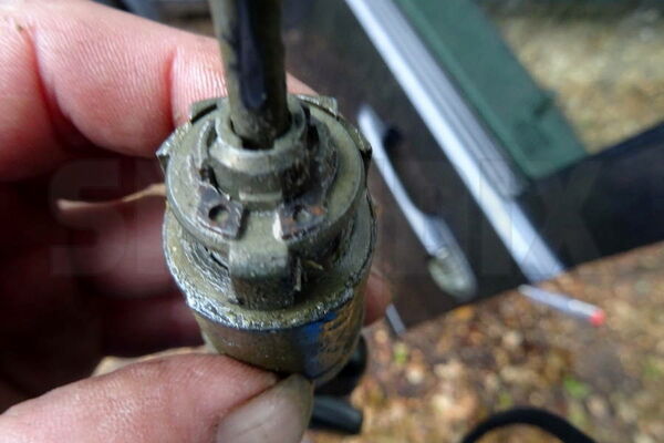
To disengage it, the circlip must be removed. The use of penetrating oil is also recommended here, it tends to be stuck in its seat.
To remove the cover with the pin, the cylinder should be in the initial position so that the springs for resetting cannot slip away. In This way, they remain in their seat.
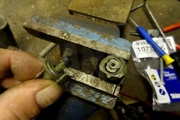
Now slide the pin out a little bit to the inside and remove the buffer rubber, now you can remove it in the right position. When mounting the new one with the new rubber, make sure that the rubber does not push the cover up too far. In this case the circlip is difficult to mount. If in doubt, shorten the rubber a little. Do not cut off too much in any case, then the pin could fall out of its guide because it is pressed into position by the rubber. The rest of the assembly is done in reverse order. Attention: Under no circumstances try to hit the retaining ring into its position with force. The middle position stop will break off very easily!
- All notes serve only as an example and do not replace the workshop instructions of the automobile manufacturers! All information is supplied without guarantee!