Conversion kit overdrive actuation
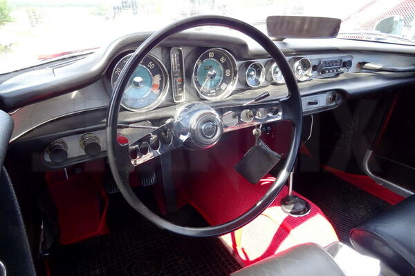
Volvo P1800
30.11.2021Instructions for converting the P1800S to a latching overdrive switch on the steering column without relay, according to the later standard in the P1800ES. This conversion requires knowledge in material processing and electrics. Adjustment work is required and the schematics and conduit colors of the early models may vary.
Warning: For all types of vehicles of such age, the dimensions and functions of the cables should be carefully checked. It is quite possible that cables or the entire wiring harness have already been replaced and line colors do not longer correspond to the original configuration. As with all work on the electrical system, be sure to disconnect the battery.
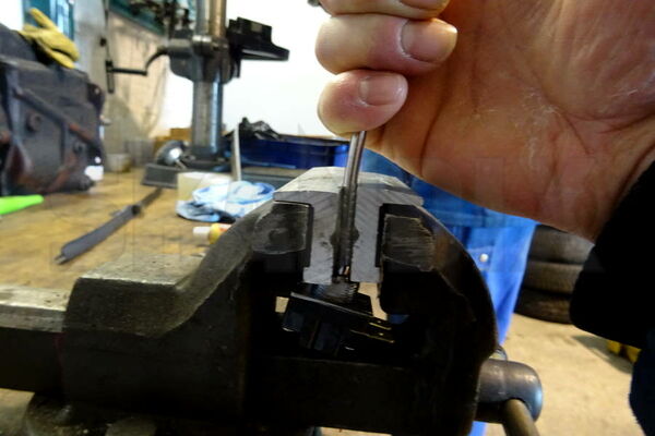
Bend open the lock washer and loosen the nut with ratchet and extension.
If the steering wheel can not be removed by hand, hold a smaller socket wrench on the attached nut and lightly hit it with a hammer, usually it releases.
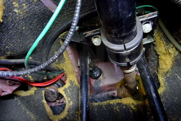
Unscrew the lower retaining clip of the steering column in the footwell.
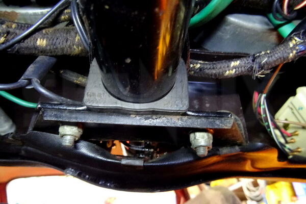
Unscrew the upper retaining clip and bracket of the steering column, remove the bracket and push clip and rubber slightly in direction of the footwell.
Unscrew and remove the three Phillips screws holding the cover of the steering column above the switches under the steering wheel.
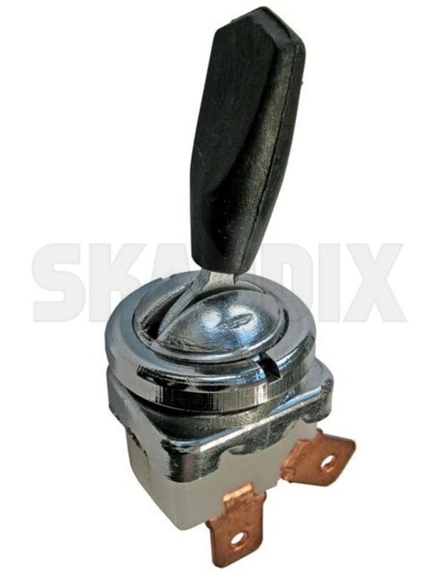
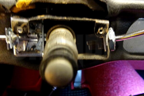
Now pull out the steering column tube until the overdrive switch can be removed to the rear. It sits in an open slot. Then loosen the nut of the switch, remove the flat plug and remove the switch.
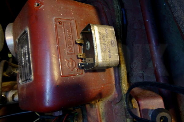
Now unscrew the overdrive relay from the vertical plate and remove all the connectors.
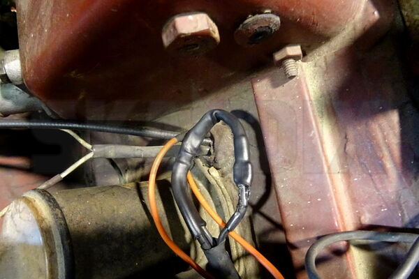
When wiring, it is essential to carefully adhere to the wiring diagrams for the vehicle, there are various versions of both the cable routing and the relays used. In this case, it is a P1800S from 1967 with a chassis number beyond 12501, there are only black and white wires connected to the relay, bridge the black wires.
The white lead is connected to the switch with a new wire.
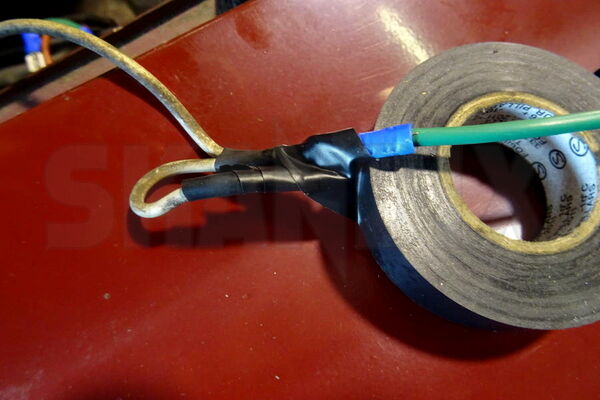
If you want to preserve the original wiring harness, crimping plugs are the simple and fail-save variant. Shrink tubing should be used for insulation (see Figure 9). Insulating tape can only be an emergency solution here. Especially with a car with only 3 fuses, you should pay close attention to a proper realization.
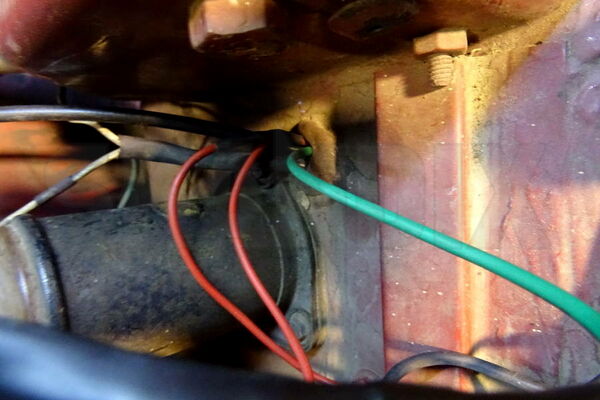
The new lead must now be pulled into the cabin to the steering column switch, this works quite well next to the choke cable.
Do not falsely fix the cable to the exposed part of the steering column!
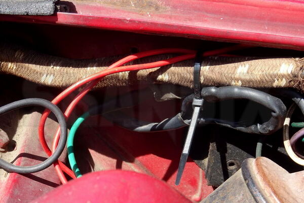
The shrunk joints must then be fixed properly, so that they do not rub anywhere or can be trapped by the hood latch, for example.
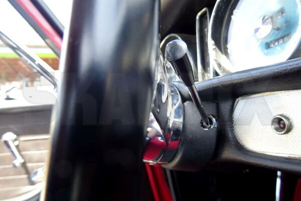
When tightening the nut of the switch, be sure to put the steering wheel on once and check that the switch is free. Otherwise, move the switch in its slot or bend the holder on the steering column slightly in the appropriate direction. Otherwise, it may happen that the steering wheel spokes hit the switch.
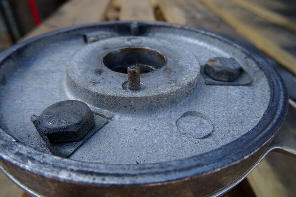
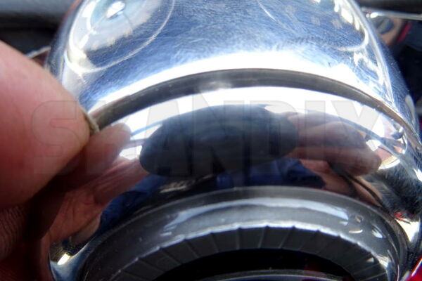
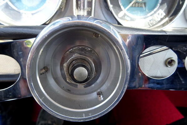
When fitting the steering wheel, make sure that the pin for the indicator reset (fig.) engages in the groove provided. Also, the combination of spring, washer and spring seat must be placed under the steering wheel in the correct order, otherwise it may malfunction.
- All notes serve only as an example and do not replace the workshop instructions of the automobile manufacturers! All information is supplied without guarantee!
Additional information...
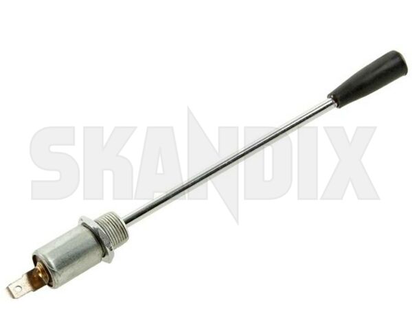
- 1071848: Overdrive switch, Control stalk Conversion kit