Repair Kit cables for cruise control drop arm
Volvo 940, 740, 760
01.12.2021Repair instruction for the cables of the cruise control functions in the drop arm of a Volvo 940 which is not longer available.
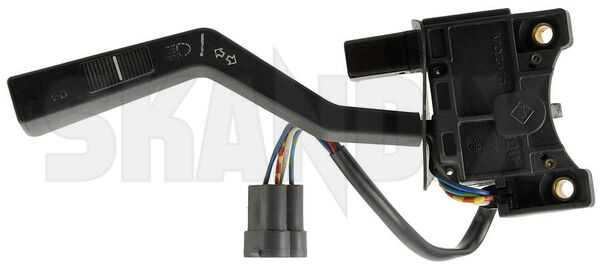
The drop arm with cruise control for the Volvo 940 isn`t available for some time. Also it`s getting harder to find functional used parts. Now we can offer you a repair kit for the frequent error of the drop arm: A cable kit for the cruise control functions. The cables are normally disconnected where they are leading into the drop arm.
For installing this repair kit, you should have a few mecanical skills, but it`s not unsolable for a well versed mecanic.
You should be versed in soldering, the cables have to be soldered on the switch board.
You should have a few skills in dismantling and mounting the switch. You also need a clean activity area where small parts won`t fade away.
Don`t repair the switch at cold temperatures, the sensitive plastic parts would be damaged earlier.
In any case you have to dismantle the drop arm and make the repair in a warm, well-lit area, where you have no carpet on the floor. Otherwise you won`t find some of the smaller parts, if they`re falling down on the floor.
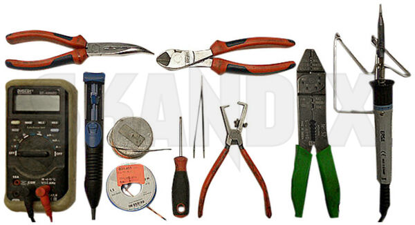
Needed tools:
-Soldering iron with tin-solder and solder-flux
-desoldering pump and litz wire
-multimeter or curcuit indicator
-two small slotted screwdrivers
-telephone pliers
-wire cutter
-wire stripper
-crimping tool
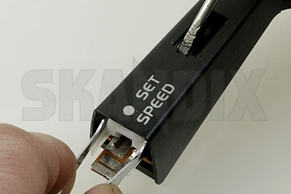
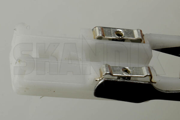
-a pair of tweezers with flat wide tips like in the picture. The tips must show a little to the inside. Without such tweezers you can`t mount the slider of the switch!
After dismantling the drop arm you have to free the cord grip of the cables. It is in front of the lower screw of the drop arm. Take it away from the cable. Then unclip the cover of the slide switch for the cruise control. The cover has two clips in the middle. With a screwdriver at both ends of the cover you can clip it off.
Take care of the small spring and ball under the cover, you have to use them again. The spring loves to jump under you working desk.
Better take the parts away carefully!
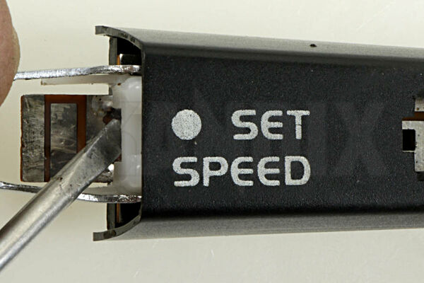
Now you see on the frontside in the outer cutout of the slider the snap-fit of the tipswitch. The other one is on the backside directly under the tipswitch. Clip them off and take away the tip cover with it`s frame, a spring, slider and a pertinax plate.
Now the small board in the drop arm is accessible. You have to pull it out of it`s seating carfully with telephone pliers while you`re pushing the cables on the steering column side. Therefore position the shrink hose directly beside the plug. Take care that the slider of the switch won`t fall out of the drop arm!
If the slider would fall out of the drop arm, the springs and the contact plates may dissappear, they are really very small.
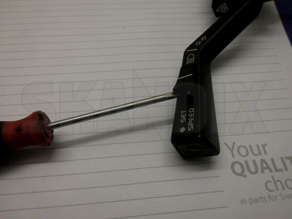
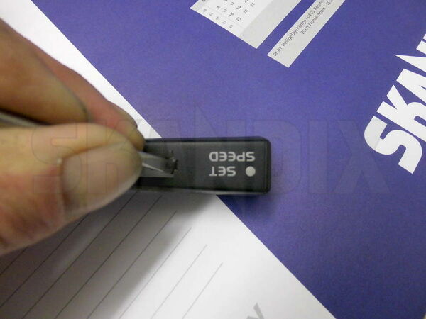
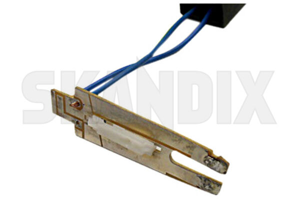
If the board is about 1cm outside of the drop arm, pull out the slider with a pair of tweezers and a screwdriver as you see in the picture above.
Position the tip of the tweezers on the springs of the slider contacts. If you pull the slider in this way, the springs won`t fly away. After this take the springs and the contacts away from the slider or fix them with an adesive strip.
If the springs would disappear at your working area, they are included in the repair kit.
The cables are long enough, so you can pull out the board for soldering with an adequate space. Now desolder the old cables an keep in your mind the right places of the four colours. Use a desoldering pump an litz wire for cleaning the soldering joints from the old tin-solder. Then you have the security of conductive solder joints and the drillholes for the cables in the board are open.
After desoldering all cables you can pull them out of the drop arm to the steering column side.
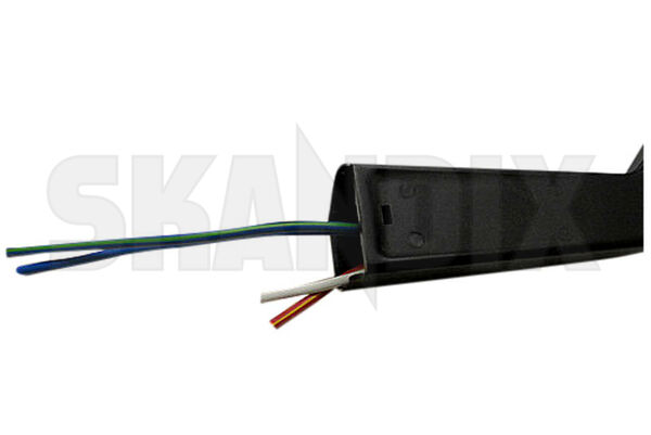
Now mount the cables singly through the drop arm. The direction is from the slider side to the steering column. If you see the cable on the column side, grip it with the telephone pliers. Pull carefully supporting with the pliers while mounting the next cable from the other side. This is a little bit tricky, especially with the third and forth cable.
If you have all of the cables mounted through the drop arm, pull the hose over the cables at the column side. If it`s positioned, strip the wires. Don`t do this before the cables are positioned, it wil be much more tricky to mount the cabels and the hose.
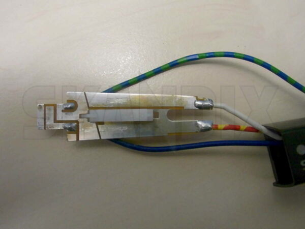
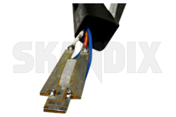
Solder the new wires on the board. Therefore put the outer ending wires into the boleholes of the board and press the litz wire down on the board.
The soldering joints needs to be flat, otherwise you can`t mount the slider.
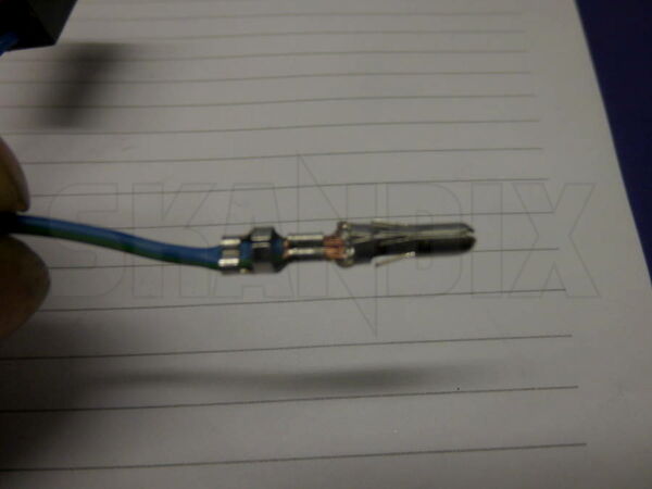
Now you can crimp the plug connectors. Please note the following points: In the small ring on the plug side you have to crimp the stripped wire. The ring in the middle will remain unaffected, it is the guidance in the plug housing. In the ring on the cable side you have to crimp the isolation.
Therefore you need two different sizes at your crimping tool.
Set the board in it`s seat in the droparm. While you do this, pull the cables out of the drop arm at the column side. Otherwise the cables would be be seize in the drop arm. Set it to the point, where the outer solder joints are flushing with the end of the drop arm.
Now you have to mount the slider: Set the spring of the contact in it`s seating, set the contact on one side an push down the spring with the contact while holding the spring in it`s seat. Set the contact in the other seat and fix it with adhesive tape, then do the same with the other contact.
If both contacts with springs are mounted, grip the slider on both sides near the springs with your tweezers and remove the adhesive strip. Holding the slider in this grip bring it in it`s seat in the drop arm. Don`t open the grip before the springs are in the seat. Otherwise they will drop out. Then push the board and the slider together in it`s final position. While doing this, pull the cables a little on the column side.

Now mount the set button. At first the pertinax underlay, then the spring, contact holder, button and frame. Clip it in, ready. Take care that nothing is canted or the spring won`t tumble down, lead it straight.
After this set the ball, spring an cover of the slider at it`s place.
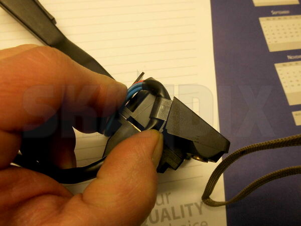
Position the hose so that it`s upper end can be clamped with the cord grip at the switch. Take care for enough clearance in the cables when you flash the light or indicate. Heat the shrink hose a little bit and clip in the cord grip.
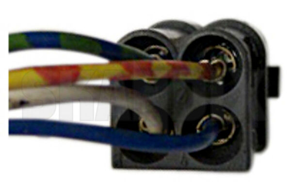
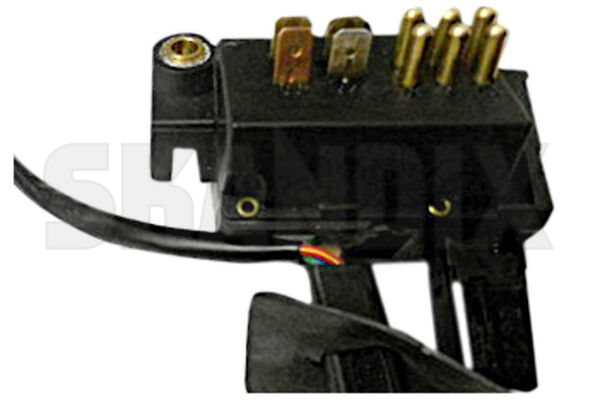
Now click the crimped plug connectors into the right places in the plug housing. Don`t make any mistake at this job, otherwise you need a special unlocking tool for the plug connectors. It is not neccesary if you do it right.
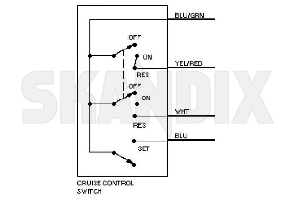
Before mounting the repaired drop arm switch, check the functions as seen on the wiring diagram with a multimeter or circuit indicator. If the board is not correct in it`s seat you may have malfunctions. The board has to be at it`s limit stop in the seating!
If there is no correct snap into the switch positions of the slider, the board position is also not correct. In this case the way of the set button is appreciable too short or the cover won`t fit.
- All notes serve only as an example and do not replace the workshop instructions of the automobile manufacturers! All information is supplied without guarantee!
Additional information...
- 1071863: Control stalk, Indicators Repair kit