Brake Servo
Volvo 121, 140
22.12.2021We show you how to replace the brake booster, including the adjustment of brake light switch and brake pedal travel. The measurements are valid for both the Volvo 140 and the Volvo Amazon. The shown car is a 1972 Volvo 145.
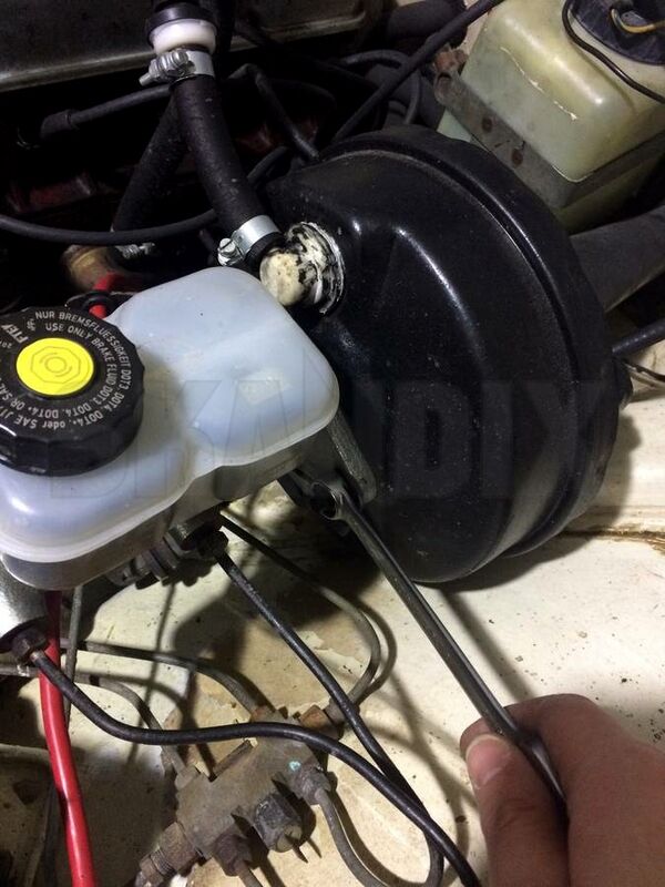
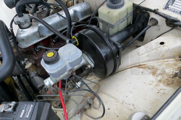
Remove the master brake cylinder and the vacuum hose between the Brake servo and the intake manifold.
The master brake cylinder can be carefully pushed to the side or completely dismantled.
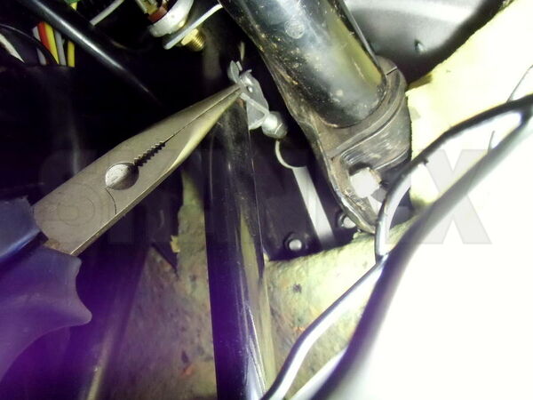
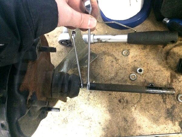
Loosen the pedal fork. Pull the splint pin. At vehicles from 1972 there is no splint pin but a nyloc nut.
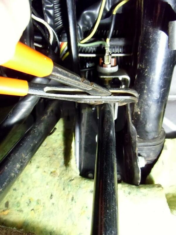
How you can remove the bolt. Stucked bolts can be pushed out with a pipe pliers.
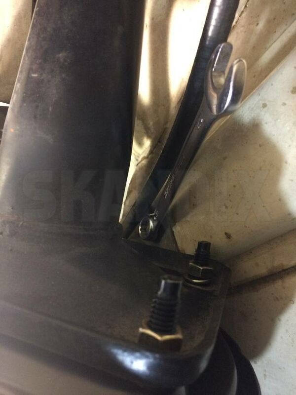
Remove the screw of the support bracket from the wheel arch.
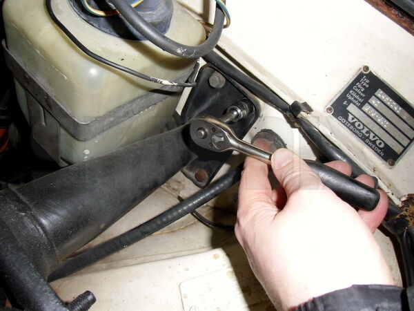
Remove the carrier from the firewall.
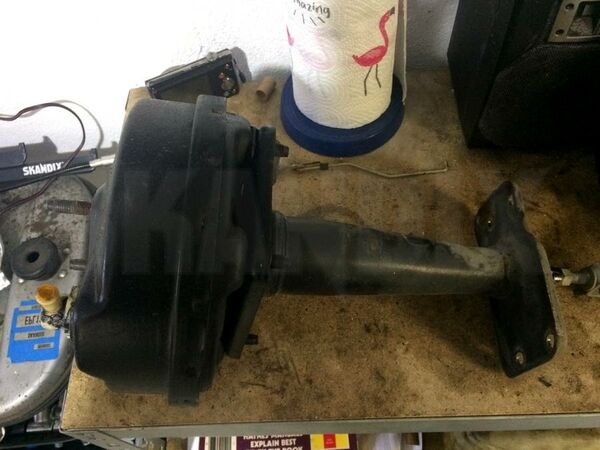
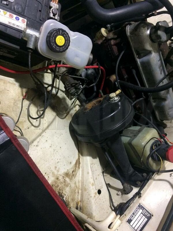
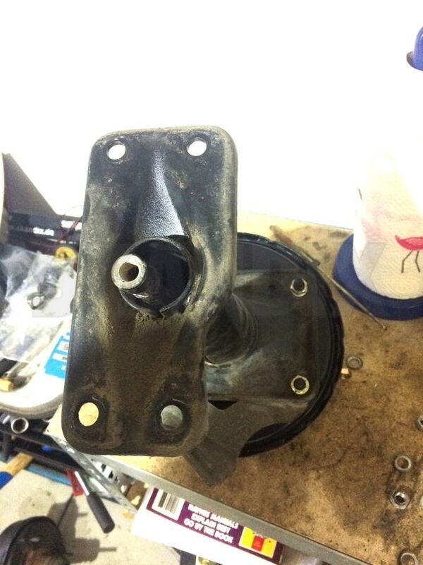
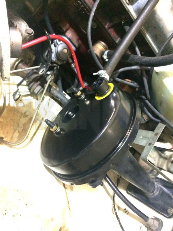
Old Brake servo with carrier.
Remove the fork from the pressure rod and pull out the rubber collar.
Remove the carrier from the Brake servo.
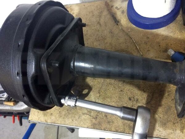
Remove the pressure rod from the Brake servo.
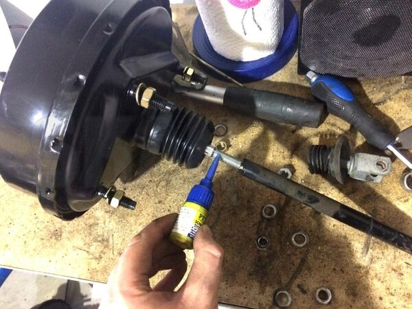
Apply chemical screwlock to the brake servo rod and attach the pressure rod. Regarding the genuine workshop manual the pressure rod must be screwed in "all the way". This does not necessarily mean in practice that the end of the thread must be reached - do not overtighten with force!
Attach the carrier and the rubber collar. Now only tighten the nuts between the brake booster and carrier by hand. Make sure that the carrier and support bracket is aligned properly.
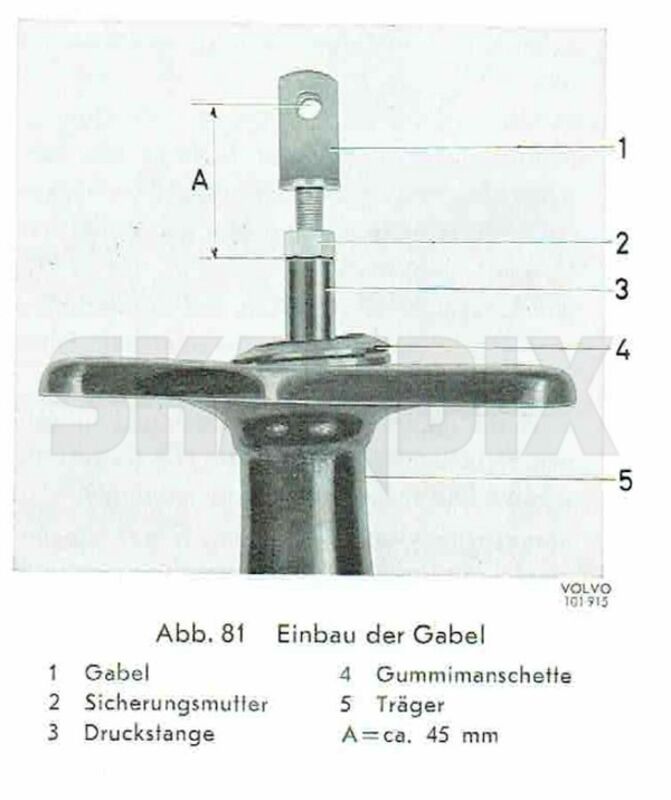
Attach the fork to the pressure rod. Do not tighten the counternut because the fork must be adjusted later.
Reinstall the brake servo and tighten in this sequence:
1. Upper Screws Carrier - Firewall
2. Screw support bracket - wheel housing
3. Lower Screws Carrier - Firewall
4. Nuts Carrier - Brake Servo
5. Connect the vacuum hose with a hose clamp.
Caution: The Brake servo outgoing pressure rod adjustment must be approved. In Rest position there must be clearance between the pressure rod and the master cylinder piston.
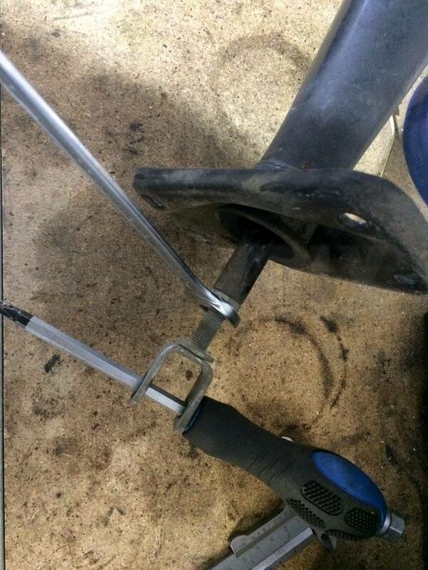
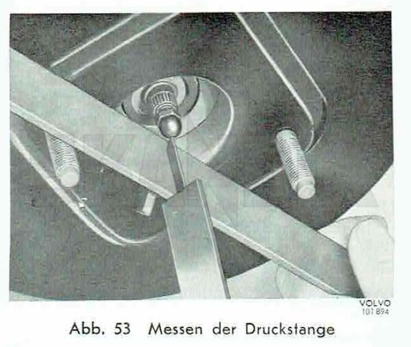
Measure how much the pressure rod (Adjustment screw) is protruding outside the power cylinder flange (Measurement B). When measuring this, the pressure rod should be completely depressed and vacuum must be present in the cylinder (Start the engine).
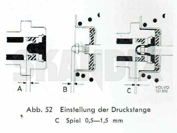
After that measure the distance between the master cylinder piston center to the flange (Measurement A). Measurement A minus measurement B makes the clearance C.
The Clearance C must be 0.5-1.5mm. The clearance can be adjusted by turn the cap nut on the Brake servo pressure rod. Apply chemical screw lock if the cap nut is turned.
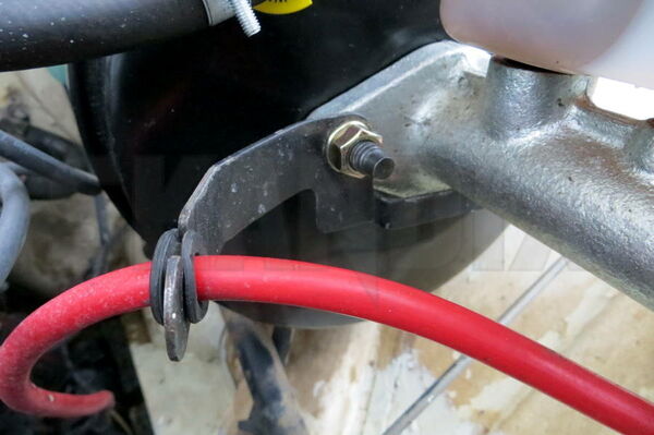
After the clearance is adjusted the master brake cylinder and the battery cable support can be installed.
If the master brake cylinder was completely dismantled the entire brake system must be bleeded.
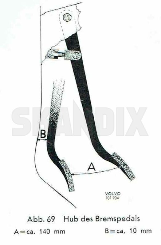
Now reconnect the brake pedal with the fork and adjust the pedal travel by turning the fork. In rest position the brake and the clutch pedal must stand in the same height if the clutch is adjusted properly. Tighten the counternut of the fork.
Use a new splint pin (1018479) for the bolt of a new nyloc nut (1008708) for screw.
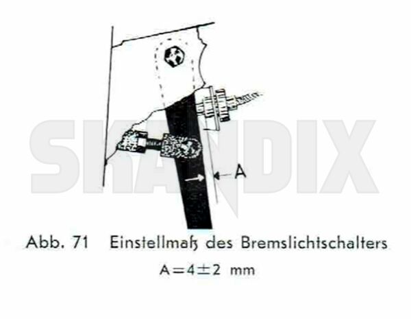
Check the brake light connect adjustment. The plastic pin must protrude 4 +/- 2mm outside the switch.
Done!
- All notes serve only as an example and do not replace the workshop instructions of the automobile manufacturers! All information is supplied without guarantee!
Additional information...
- 1046323: Brake booster