Sensor, Crankshaft pulse
Saab
23.11.2021Saab 900 / 9000 OE Crank Shaft Sensor, repair kit
(OE ref p/n 7484546, 7482540, 9133067 & 8786246)
Model:
900
1989-1993 B202 & B212 injection with EZK ignition (3 pin rectangular plug)
9000
1989-1991 B202 with EZK ignition (3 pin square plug)
1992 B202 with EZK ignition
1990-1991 B202 with red DI cassette (3 pin square plug)
1992 B202 engine turbo or non turbo with red DI cassette
1990-1991 B234 engine, turbo or non turbo with red DI cassette
1992 B234 engine, turbo or non turbo with red DI cassette
Instructions / Fitting Tips
Caution, this sensor maybe damaged if wired incorrectly. Please check the existing wiring harness and determine the +12V and earth connections and refer to the wiring diagram below.

Sensor Lead Wire Termination
black (ground)
green (signal)
red (+12V)
These instructions are for the Classic 900 Sensor. For the 9000 sensor use these instructions as a guide.
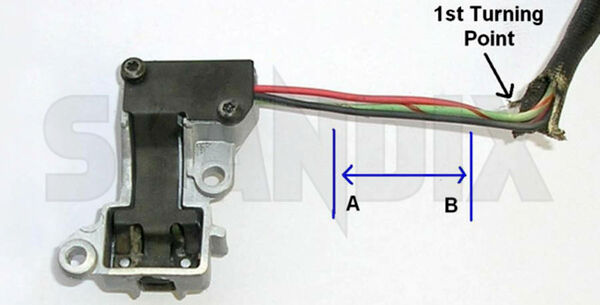
1. Remove the existing sensor housing from the motor, mark all tight inflection points in the cable route. Please note that at the first turning point no connecting sleeves must be mounted to avoid damage to the signal path.
2. The work area should be clean and it´s surface should be made of non-conductive, non-ferrous material. After removing the old sensor from the housing, clean it and remove it from all oil, dirt, grease and metal residues.
3. Decide if the new sensor will be installed using either
a) Three staggered joints (recommended) OR
b) Three equal length joints.
4. Push back the old black thermal insulating sleeve and cut off the old sensor head between points ?A? and ?B? and before the 1st turning point.
5. The new black thermal sleeve is pre-cut to the correct length.
Attach a rigid rod / wire to the three leads of the old wiring harness and slide off the old black thermal sleeve. Feed the rod into the NEW black thermal sleeve and push back the sleeve to expose the three leads.
6. Trim the three new sensor leads to the same length as the old sensor adding 1 to 2cm to the length. Slide on the heat shrink tubing over each of the three old leads.
7. Solder the three joints (recommended). Alternatively, use the enclosed crimp connectors. Cover each joint with the heat shrink tubing and shrink to fit.
8. Push the thermal sleeve down to the sensor head. Install the new sensor into the housing.
9. Referring to the picture below, the thermal sleeve needs to be reduced in diameter to correctly fit into the housing.
- a) Between points ?C? & ?D? fold the thermal sleeve along its length and double back onto its self. Fit into the cable grip section of the housing.
- b) Between points ?E? & ?F?, make a cut of 20 -> 25mm at the end of the sleeve. Tightly fold one end of the sleeve end inwards and fold the other end inwards tightly overlapping the first fold.
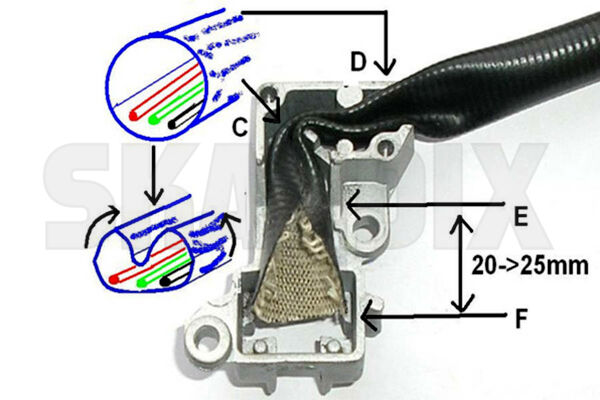
Important: When correctly fitted, the sleeve will fit inside the cable channel of the housing without protruding over the edges (between points E & F) and sits flush with the top of the cable grips between C & D.
10. Refit the sensor back plate into the housing ensuring that it sits flush with the housing.
11. Clean the old vane wheel / trigger disc of any oil, dirt and other contaminations.
12. Before installing the sensor, check that the sensor is working correctly. Connect the sensor leads to the wiring harness and with the ignition switched on, check that an approximate +5.0V signal is produced when a solid section of the trigger wheel is placed between the sensor heads. This voltage should be reduced down to approximately +0.1V when the cut out section of the trigger wheel passes over the sensor head.
13. Avoid scraping the sensor head with the trigger wheel when performing this test.
- All notes serve only as an example and do not replace the workshop instructions of the automobile manufacturers! All information is supplied without guarantee!
Additional information...
- 1024739: Sensor, Crankshaft pulse