Brake booster, fitting Instructions
Volvo PV, 121, P1800
23.11.2021Important specific and general instructions on the installation of a brake booster and any work on the brake system.
For single line braking systems.
General fitting instructions
To ensure correct installation of the remote vacuum servo unit, thoroughly read and adhere to the fitting instructions prior to carrying out any work on the vehicle.
Introduction
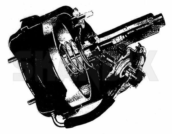
The vacuum servo unit Is incorporated into the hydraulic braking system, remote from the master cylinder, as an intermediate stage operating between the master cylinder and the brake assemblies. The two main parts of the servo unit consist of the vacuum servo mechanism and the hydraulic slave cylinder assembly. These component parts are bolted together so that the slave cylinder piston is in line with, and Is operated directly by, the servo push rod.
A plastic non"`return valve is fitted into the vacuum shell and an integral air cleaner incorporated to prevent foreign matter entering the air control valve chamber.
The servo unit is designed to give no assistance with very light brake application. In the absence of servo assistance due to loss of vacuum, an unrestricted passage for the fluid will exist. The·brake can still be applied, therefore, by the normal action of the pedal on the brake master cylinder, but this would demand heavier foot pressure to achieve the same degree of·braking as with servo assistance. When this servo unit is used to replace a non-Lockhead server is installed on a vehicle previously without a servo, the following installation recommendations must be observed.
Note: Not for use on vehicles with tandem or dual line braking systems except for specific applications where twin servo units are fitted. In this instance, units must be replaced in pairs to maintain the correct brake balance.
Important:
Fitting a brake servo unit will not make faulty brakes reliable. .Any fault in the vehicle braking system must be rectified. Therefore before fitting the new servo unit, ennsure that the braking system is in good working order.
Note:
A. When changing brake parts the need for absolute cleanliness
is essential. Therefore ensure that hands are free or grease and dirt. Always use fluff-free cloth or paper toweling for cleaning purposes.
B. Ensure a sufficient quantity of the corrrect brake fluid is available for bleeding the braking system and topping up the reservoir. Where·possible brake fluid should·always be stored and dispensed from the original tin or bottle. Care must be taken·to prevent both dirt entry and contamination especially in the mouth area of the master cylinder reservoir during the operation.
Prior to fitment of the brake servo unit or removal of an existing servo installation, thoroughly clean the outer surfaces of the unit (where applicable) an around all relevant hydraulic pipe connections using methylated spirit as solvent. Do not use petroleum-based products for cleaning braking system components, i.e. petrol or paraffin.
On the majority of vehicles a 3-way adaptor is used into which are coupled the supply pipe from the master cylinder outlet port and the pipes feeding both front an drear brake assemblies.
Removing existing Installation
1. Disconnect·the battery.
2. Disconnect and remove the vacuum hosepipe that connects the servo unit to the vacuum pump/manifold.
3. Disconnect, remove and discard the hydraulic feed pipe from the master cylinder outlet port to the 3.way adaptor. Sea off the hydraulic connection points to prevent loss of brake fluid and ingress of foreign matter.
4. Unbolt the existing servo unit together with any mounting brackets, where applicable, and remove from the vehicle.
Note:
Brake fluid is injurious to paintwork, therefore when removing the servo unit from the vehicle care should be taken to ensure that no fluid is spilt onto the painted surface of the bodywork. Should fluid spillage occur, wash of immediately with copious amounts of cold water.
The following general instructions apply to remote servo installation kits. Obviously all vehicle types cannot be quoted, but by observing these instructions the installation kit can be used for the majority of vehicles with single line braking system.
Where the hydraulic piping, supplied in the fitting kit, needs to be shortened it will be necessary to use a Bundy flaring too to reform the pipe end.
Location of new servo unit and brackets
1. it is essential that the servo unit is fitted to the integral body or chassis (i.e. Not to the engine) thus preventing the brake pipes being subjected to vibration or flexing.
2a. It is an advantage to locate the servo within the engine compartment whenever possible to safeguard the unit and to keep the hydraulic pipe runs to a minimum length.
2b. Should it become necessary to fit the servo unit in an area on the vehicle prone to dirt, grit or water ingress e.g. under body wings, it is recommended that an extension hose be fitted to the air control valve inlet by carrying out the following modification, prior to installation.
Method:
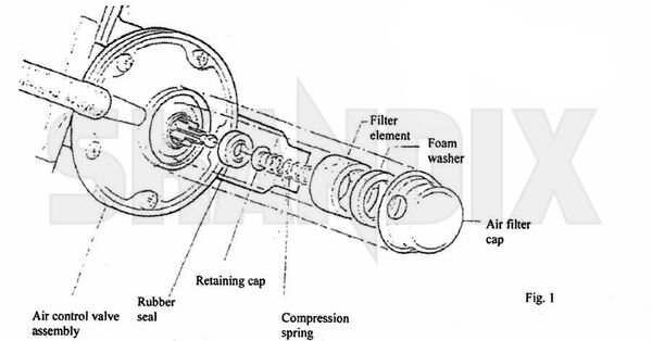
Carefully prize off the plastic air filter cap. Note components retained by the cap, which is snap fit, may become dislodged during removal. Therefore care must be taken to prevent parts becoming lost or damaged. Extract the form within the existing air filter cap and replace. Fit the air filter cap to the air control valve ensuring that the rubber seal, seal retaining cap, compression spring and filter element are all correctly located. (See Fig.1 for details). Connect one of the vacuum hoses from the kit to the inlet pipe on the filter cap,secure with clip provided. On installation, locate the other end of the vacuum hose in a suitable position away from dirt or grit.
3. Ensure the hydraulic slave cylinder is at least six inches away from any part of the vehicle exhaust system, otherwise fluid vaporization from local heat occur.
4. The servo unit need not be mounted below the level of the brake fluid reservoir, but keep the difference in height to minimum.
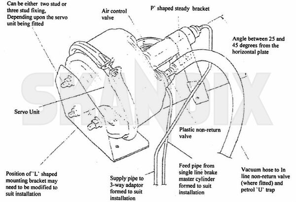
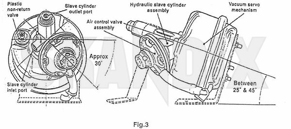
5. With the aid of the mounting brackets and fixings provided in the kit install the servo unit with the hydraulic slave cylinder outlet port inclined upwards between 25° and 45° from the horizontal plane. (See, Fig.2). The air control valve should be situated at least 30° below the centre line to assist when bleeding the hydraulic system. (See Fig.3).
Fitting hydraulic piping
With all relevant connection points clean and free from ingress of foreign matter, using the new Bundy piping supplied in the kit:
a. Connect up the feed pipe from the brake master cylinder to the servo slave cylinder inlet port.
b. Connect up the supply pipe from the servo slave cylinder outlet port to the 3-way adaptor.
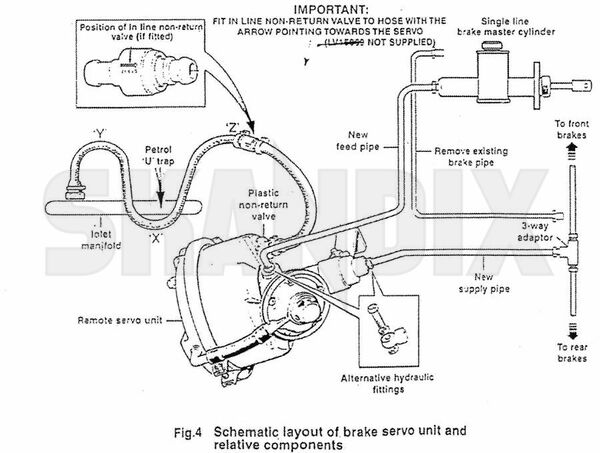
When bending brake pipes to shape, great care must be taken to avoid kinking. The best way to obtain a good curve is to bend the pipes smoothly round a mandrel of suitable diameter. Using existing clips on the vehicle, ensure pipes are properly secured and cannot chafe or foul other components. Where a long length of piping is fitted e.g. from one side of the vehicle to the other via the bulkhead, secure the pipe to the bulkhead to avoid vibration, Additional pipe clips are available for use where necessary. On some vehicles where space is limited, it will be helpful to use banjo and bolt fittings in the tappings of the servo slave cylinder to avoid a server bend in the brake pipe. (See Fig.4).
Note:
Not attempt should be made to cut and reflare existing brake pipes in situ, as problems could arise with contamination through ingress of foreign mater, i.e. swarf.
Vacuum hose, In line non-return valve (where fitted), and fittings
The servo unit must be connected via a vacuum hose, running from the plastic non-return valve located in the servo shell to a suitable vacuum source e.g. the engine induction manifold or vacuum pump. On some vehicles the manifold is already tapped and fitted withe a removable plug, otherwise it will be necessary to drill and tap the manifold.
Three manifold adaptors are available, each with a different thread size to suit various applications.
These thread sizes are:
1. 1/8" B.S.P. taper. This is self-sealing and should be used when the manifold is not already tapped. Drill the top wall of the manifold 5/16" and tap with a 1/8" B.S.P taper tap. The manifold should be removed from the engine for this operation.
2. 5/8" x16 Whitworth thread. (Use with a copper gasket).
3. 5/8" x18 U.N.F thread (USe with a copper gasket).
Fit the relevant adaptor (and the copper gasket, if a 5/8" diameter adaptor is used), and attach the vacuum hose from the kit, securing with one of the hose clips provided.
In a convenient position, preferably at the highest point in the vacuum hose run, an in line non-return valve is advisable on high performance vehicles. Cut the hose and connect up the the two sections to the valve unit, secure with hose clips supplied. Ensure that when fitted the arrow on the non-return valve is pointing towards the servo. (See Fig.4).
Important:
To protect the servo unit and non-return valve from fuel contamination, especially on a petrol engined vehicle, a ` U` trap must be formed in the vacuum hose route.
It is essential the vacuum hose inlines downwards from the servo and the ` U` trap is formed below the level of the servo and in line non-return valve (where fitted), i.e. by looping it between the inlet manifold and non-return valve so that point `x` is lower than points ` Y` and ` Z` as shown (See Fig 4). Where the vacuum hose traverses the engine secure in position with plastic ties. Secure hose connection at the servo with the remaining hose clip.
Bleeding and testing system
1. Reconnect the battery.
2. Using new brake fluid as recommended by the vehicle manufacturer (conforming to SAE specification) bleed the braking system in accordance with the appropriate vehicle manual. With the system properly bled, firm resistance should be felt at the break pedal, if difficulty is experienced in achieving a good bleed, then the bleeding process will be assisted by "cracking open" the brake pipe tube nut at the servo outlet connection whilst depressing the brake pedal. Surround this connection with clean "fluff free" cloth to capture escaping brake fluid. When the pedal is fully depressed retighten tube nut, repeat this process several times if necessary. When completed, "top up" the fluid reservoir to the correct level.
3. Start the engine and apply the brakes several times. Whilst an assistant depresses the brake pedal, re-check for fluid leaks.
4. Particularly where new connections have been made. Road test the vehicle, and finally check the fluid leaks.
- All notes serve only as an example and do not replace the workshop instructions of the automobile manufacturers! All information is supplied without guarantee!